The Genie IntelliG 1000 garage door opener is part of the Professional Line, offering a powerful DC motor, quiet operation, and advanced features for reliability and performance.
Designed for seamless integration with various garage door styles, this model provides a comprehensive guide for installation, operation, and maintenance, ensuring compatibility and ease of use.
1.1. Overview of the Genie IntelliG 1000 Garage Door Opener
The Genie IntelliG 1000 is a high-performance garage door opener designed for reliability and smooth operation. It features a durable DC motor, screw/belt/chain drive options, and advanced Intellicode technology for secure wireless communication. With a focus on quiet operation and ease of use, this model is part of Genie’s Professional Line, ensuring compatibility with various garage door systems. Its compact design and user-friendly interface make it a versatile choice for homeowners seeking efficient and dependable garage door solutions.
1.2. Key Features and Benefits
The Genie IntelliG 1000 offers a powerful DC motor for smooth and quiet operation, along with advanced Intellicode technology for enhanced security. It features programmable limits for precise door travel control and force control settings to ensure safe operation. The opener is compatible with various accessories, including remote controls, wall consoles, and keypads, and integrates seamlessly with HomeLink systems. Its robust design and user-friendly programming make it a reliable and efficient choice for homeowners. Regular maintenance tips and troubleshooting guides are provided to ensure optimal performance and longevity of the product.

Safety Information and Precautions
Read and follow all safety, installation, and operation instructions carefully. If questions arise, contact The Genie Company for clarification to ensure safe and proper use of the IntelliG 1000.
2.1. General Safety Guidelines
Always follow safety precautions to avoid accidents. Keep children away from moving garage doors and ensure they do not play with the remote or wall controls. Never stand under a moving garage door, and ensure it is properly closed when unattended. Avoid touching electrical components and ensure all connections are secure. Wear protective gear during installation or maintenance. Regularly inspect the door and opener for wear or damage. If unsure about any procedure, consult the user manual or contact The Genie Company for assistance to ensure safe operation and maintenance of the IntelliG 1000.
2.2. Important Safety Precautions During Installation
Follow all safety instructions carefully during installation to prevent accidents. Always wear protective gear, such as gloves and safety glasses. Ensure the garage door is fully closed and locked before starting installation. Disconnect power to the old opener, if applicable. Never install the opener while standing on an unstable ladder or surface. Keep children and pets away from the work area. Avoid installing in wet conditions or near water sources. Use a GFCI-protected outlet for electrical connections. If unsure about any step, consult the user manual or contact The Genie Company for professional assistance to ensure a safe and proper setup of the IntelliG 1000.
2.3. Safety Features of the Genie IntelliG 1000
The Genie IntelliG 1000 incorporates advanced safety features, including the Safe-T-Beam system, which detects obstacles in the door’s path, preventing accidents. The opener is equipped with an automatic reversal mechanism that stops and reverses the door if it encounters resistance. Additionally, the Intellicode technology ensures secure operation by rolling code encryption, preventing unauthorized access. These features enhance user safety and provide peace of mind while operating the garage door opener. Regular maintenance of these systems is crucial to ensure optimal performance and continued safety.

Installation Instructions
Installation of the Genie IntelliG 1000 requires careful preparation and adherence to the provided manual. Ensure all components are included and follow step-by-step guides for proper setup.
3.1. Preparation for Installation
Before installing the Genie IntelliG 1000, ensure you have all components, including the powerhead, rail, belt or chain, and hardware. Read the manual thoroughly to understand the process.
- Unpack and organize all parts to avoid missing items.
- Verify compatibility with your garage door size and type.
- Gather necessary tools like a ladder, wrench, and screwdrivers.
- Ensure the garage door is balanced and properly aligned.
Preparation is key to a smooth installation process. Follow safety guidelines and double-check all parts before starting.
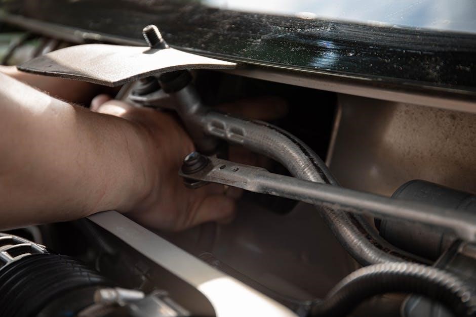
3.2. Step-by-Step Installation Guide
Install the Genie IntelliG 1000 by following these organized steps:
- Assemble the rail and attach it to the powerhead.
- Mount the powerhead securely to the garage ceiling, ensuring proper alignment.
- Attach the door arm to the garage door and connect it to the trolley.
- Install the safety sensors 6 inches above the floor on both sides of the door.
- Connect and wire the wall console, keypad, and sensors to the powerhead.
- Test the door’s operation to ensure smooth and safe functionality.
Refer to the manual for detailed instructions and safety precautions during installation.
3.3. Common Installation Mistakes to Avoid
Avoid these common errors when installing the Genie IntelliG 1000:
- Incorrect alignment of the powerhead with the garage door tracks.
- Improper tightening of the door arm, leading to unstable operation.
- Failure to level the sensors correctly, which may disrupt safety features.
- Not securing the trolley properly to the door arm.
- Incorrect wiring of the wall console or keypad.
- Not testing the door’s full range of motion after installation.
Always follow the manual’s instructions to ensure a safe and proper setup.

Operating the Genie IntelliG 1000
Operating the Genie IntelliG 1000 involves using the remote control, wall console, and HomeLink system for seamless door operation. Refer to the manual for detailed instructions.
4.1. Understanding the Remote Control
The Genie IntelliG 1000 remote control utilizes IntelliCode technology for secure communication. It offers easy operation with a compact design, featuring buttons for opening, closing, and light control. The remote is pre-programmed but can be synchronized with the garage door opener if issues arise. Regular battery replacement ensures consistent performance. The remote operates within a 200-foot range, providing convenience for users. Always refer to the manual for specific programming instructions to ensure proper functionality and compatibility with your system.
4.2. Using the Wall Console and Keypad
The wall console and keypad provide convenient control for the Genie IntelliG 1000. The wall console includes buttons for opening, closing, and turning on the light. The keypad allows secure access by entering a programmed PIN. Programming the keypad involves syncing it with the opener using the remote control. The console also features indicators for system status and battery level. Regularly cleaning the keypad and ensuring proper power supply ensures reliable operation. Always refer to the manual for detailed programming and maintenance instructions to maximize functionality and security.
4.3. Programming the HomeLink System
Programming the HomeLink system for the Genie IntelliG 1000 allows seamless integration with your vehicle. Start by pressing and holding the HomeLink button until the indicator light flashes. Press the garage door opener remote simultaneously, then release. The light will flash rapidly, confirming synchronization. Test the system by pressing the HomeLink button to ensure the door opens or closes. Refer to the manual for specific timing and compatibility details, as IntelliG 1000 supports both IntelliCode 1 and 2 signals. Troubleshooting tips are also available in the manual for any connectivity issues.

Maintenance and Troubleshooting
Regular maintenance ensures smooth operation. Lubricate moving parts annually and inspect the belt or chain for wear. Troubleshoot issues like misaligned sensors or door imbalance promptly.
5.1. Regular Maintenance Tips
Regular maintenance is crucial for optimal performance. Lubricate moving parts annually, inspect sensors for alignment, and check the chain or belt for wear. Ensure the door is balanced and operates smoothly. Refer to the owner’s manual for detailed instructions. Additionally, clean the garage door tracks and rollers to prevent debris buildup. Always disconnect power before performing maintenance tasks. Addressing minor issues promptly prevents major repairs. Follow these tips to extend the lifespan and reliability of your Genie IntelliG 1000 garage door opener.
5.2. Troubleshooting Common Issues
Identify and resolve issues quickly with troubleshooting steps. If the door doesn’t open, check remote batteries and ensure the opener is plugged in. For misalignment, adjust sensors and ensure they’re clean. A door that reverses may need force settings recalibrated. Refer to the manual for detailed solutions. Resetting the opener can often resolve remote synchronization problems. Regular maintenance helps prevent these issues. Always follow safety guidelines when troubleshooting to avoid accidents. Consult the user manual or contact support if problems persist.
5.3. Resetting the Garage Door Opener
Resetting the Genie IntelliG 1000 restores factory settings, resolving synchronization issues. Press and hold the “Learn” button until the LED turns off, then release and press twice. This clears all remote and keypad settings, requiring reprogramming. Ensure the door is closed before resetting to avoid unintended movement. After resetting, reprogram remotes and keypads as outlined in the user manual. This process ensures optimal performance and security for your garage door system. Regular resets can help maintain smooth operation and prevent recurring issues. Always refer to the manual for detailed instructions.

Programming and Configuration
Programming the Genie IntelliG 1000 involves setting door travel limits, remote synchronization, and force control. Follow manual instructions for precise adjustments and optimal performance. Ensure proper setup for smooth operation and safety.
6.1. Limits Programming for Door Travel
Limits programming on the Genie IntelliG 1000 allows you to set the door’s travel range for opening and closing. This ensures the door stops at the correct positions, preventing damage or obstruction. Properly setting these limits is essential for safe and efficient operation.
To program the travel limits, press the Set button on the powerhead and adjust the positions using the remote control. Follow the manual’s instructions for precise calibration. This feature ensures your garage door operates smoothly and reliably, adapting to your specific setup and needs.
6.2. Remote Programming and Synchronization
Programming the remote for the Genie IntelliG 1000 ensures it syncs with the garage door opener. Use the Learn button on the powerhead to pair the remote. Press and release the Learn button, then press the remote control button to synchronize. This process ensures secure communication between devices. For multiple remotes or keypads, repeat the steps to sync each device. Proper synchronization guarantees reliable operation and prevents unauthorized access, enhancing safety and convenience for users.
Refer to the manual for detailed steps to ensure accurate programming and synchronization.
6.3. Adjusting Force Control Settings
Adjusting the force control settings on the Genie IntelliG 1000 ensures smooth operation. The force determines how much power the motor uses to open or close the door. Use the adjustment screws on the powerhead to increase or decrease the force. Ensure the settings are balanced to avoid straining the motor or damaging the door. Proper calibration prevents excessive noise and wear, ensuring safe and efficient operation. Always test the door after adjustments to confirm it opens and closes smoothly. Refer to the manual for precise instructions to achieve optimal force settings.
Regular checks of these settings are recommended to maintain performance.

Accessories and Compatibility
The Genie IntelliG 1000 supports various accessories, including remote controls, wall consoles, and keypads, ensuring enhanced functionality. It is also compatible with home automation systems for seamless integration.
7.1. Compatible Remote Controls and Keypads
The Genie IntelliG 1000 is compatible with a range of remote controls and keypads, including the standard remotes provided and optional wall-mounted keypads for added convenience. These accessories utilize IntelliCode technology, ensuring secure and reliable communication with the garage door opener. The system supports both IntelliCode 1 and IntelliCode 2 signals, making it backward compatible with older Genie models. Users can easily synchronize their remotes and keypads with the IntelliG 1000, providing seamless control over their garage door. Additional keypads can be installed for multiple access points, enhancing functionality and user experience.
7.2. Optional Accessories for Enhanced Functionality
The Genie IntelliG 1000 can be enhanced with optional accessories to improve functionality; These include additional remote controls, keypads, and smart device integration options. The GenieWall Console provides convenient wall-mounted control, while the GenieKeyless Entry Keypad offers secure, PIN-based access. For advanced users, compatibility with systems like HomeLink and Aladdin Connect allows seamless integration with vehicles and home automation systems. These accessories ensure that the IntelliG 1000 can adapt to various user needs, providing enhanced convenience and control over garage door operations.
7.3. Compatibility with Home Automation Systems
The Genie IntelliG 1000 is compatible with various home automation systems, enhancing its functionality and integration with smart home setups. It works seamlessly with systems like HomeLink and Aladdin Connect, allowing users to control their garage door via smartphone apps or voice commands through smart speakers. This compatibility enables features such as remote monitoring, scheduled operations, and voice control, making it a versatile choice for modern homes. The IntelliG 1000’s adaptability ensures it can be easily incorporated into existing smart home ecosystems for a seamless and connected experience.

Technical Specifications
The Genie IntelliG 1000 features a robust DC motor, offering quiet and efficient operation with a 1-horsepower output, suitable for standard residential garage doors, and operates at 120V.
8.1. Motor and Gearbox Specifications
The Genie IntelliG 1000 is equipped with a powerful DC motor, delivering smooth and quiet operation. The motor operates at 120 volts, providing a reliable 1-horsepower output. The gearbox is designed for durability, ensuring long-lasting performance with minimal noise. This combination makes the IntelliG 1000 suitable for standard residential garage doors, offering efficient and consistent operation. The motor and gearbox work together seamlessly to provide smooth door movement, reducing wear and tear on both the opener and the door itself.
8.2. Operating Noise Levels
The Genie IntelliG 1000 is designed with noise reduction in mind, featuring a DC motor that operates quietly. Its belt or chain drive system minimizes vibrations and noise during operation. The opener is ideal for garages near living spaces, ensuring minimal disruption. With a noise level significantly lower than traditional openers, the IntelliG 1000 provides a peaceful environment. Its advanced engineering ensures smooth, quiet performance, making it a great choice for homeowners seeking both reliability and reduced noise.
8.3. Warranty Information
The Genie IntelliG 1000 garage door opener is backed by a comprehensive warranty program. The motor is covered under a 10-year limited warranty, while the parts and accessories are protected by a 2-year limited warranty. These warranties ensure long-term reliability and performance.
The warranty is non-transferable and applies only to the original purchaser. For detailed terms and conditions, refer to the owner’s manual or contact The Genie Company directly. This warranty underscores Genie’s commitment to quality and customer satisfaction.

User Manuals and Resources
The Genie IntelliG 1000 user manual is available online for free download in PDF format, providing detailed installation, operation, and maintenance instructions. Additional resources include FAQs, troubleshooting guides, and video tutorials to support users effectively.
9.1. Downloading the User Manual
The Genie IntelliG 1000 user manual is readily available for download on the official Genie Company website. Simply navigate to the support section, enter your model number (3024), and select the appropriate document. The manual is provided in PDF format, ensuring easy access and readability across all devices. It includes detailed instructions for installation, operation, and troubleshooting, as well as safety guidelines and warranty information. For convenience, the manual can also be found on third-party platforms like ManualsBase or ManualsLib. Always ensure you download from trusted sources to avoid unauthorized content.
9.2. Online Support and FAQs
The Genie Company offers extensive online support for the IntelliG 1000 model. Visit their official website to access a dedicated FAQ section, addressing common queries about installation, operation, and troubleshooting. Additionally, users can find detailed product information, troubleshooting guides, and video tutorials. For direct assistance, customers can contact Genie’s customer support team via phone or email. The support page also provides model-specific resources, ensuring users can resolve issues efficiently without needing to consult external sources. This comprehensive support system enhances the overall user experience and product reliability.
9.3. Video Tutorials and Guides
Genie provides an extensive library of video tutorials and guides for the IntelliG 1000 model. These resources, available on the official Genie website and YouTube channel, cover topics like installation, remote programming, and troubleshooting. Step-by-step instructions and visual demonstrations make complex tasks easier to understand. Videos are updated regularly to address common issues and new features. This visual support complements the user manual, offering an alternative learning method for users who prefer hands-on guidance. The tutorials are designed to help users troubleshoot and maintain their garage door opener with confidence and efficiency.

Comparison with Other Genie Models
The IntelliG 1000 stands out among Genie models like SilentMax 1000 and ChainMax 1000, offering a DC motor for quieter operation and advanced force control settings.
10.1. IntelliG 1000 vs. SilentMax 1000
The IntelliG 1000 and SilentMax 1000 differ in their core technologies. The IntelliG 1000 features a DC motor with variable speed control, while the SilentMax 1000 uses a belt-drive system for quieter operation; Both models offer advanced safety features like obstacle detection and remote programming capabilities. However, the IntelliG 1000 includes additional force control settings, making it more customizable for specific garage door needs. The SilentMax 1000 excels in noise reduction, making it ideal for homes where quiet operation is a priority. Both models are compatible with HomeLink systems and Genie accessories, ensuring seamless integration into smart home setups. Choose based on noise preference or customization requirements.
10.2. IntelliG 1000 vs. ChainMax 1000
The IntelliG 1000 and ChainMax 1000 are both reliable garage door openers but cater to different needs. The IntelliG 1000 features a DC motor with variable speed control, offering quieter operation and smoother performance. In contrast, the ChainMax 1000 uses a robust chain-drive system, known for durability and strength, making it suitable for heavier garage doors. Both models include essential safety features like obstacle detection and remote programming. However, the IntelliG 1000 provides additional customization options, such as force control settings, while the ChainMax 1000 prioritizes raw power and longevity. Choose based on your specific garage door requirements and operational preferences.
10.3. IntelliG 1000 vs. TriloG 1200
The IntelliG 1000 and TriloG 1200 are both advanced garage door openers from Genie, each offering unique features. The IntelliG 1000 is known for its quiet operation, DC motor efficiency, and compact design, making it ideal for residential use. The TriloG 1200, while similar, offers enhanced speed and a robust gearbox, suitable for heavier doors and high-traffic usage. Both models support HomeLink programming and IntelliCode technology for secure remote access. However, the TriloG 1200 has a higher horsepower, making it better for industrial or commercial applications, whereas the IntelliG 1000 excels in residential settings with its noise-reducing capabilities.
The Genie IntelliG 1000 is a reliable and efficient garage door opener, offering a powerful DC motor and quiet operation. Its comprehensive manual ensures easy installation and maintenance, making it an excellent choice for homeowners seeking quality and innovation.
11.1. Final Thoughts on the Genie IntelliG 1000
The Genie IntelliG 1000 stands out as a dependable and feature-rich garage door opener, offering smooth operation and robust performance for various garage door types.
Its advanced features, such as limits programming and force control, ensure safe and efficient functionality, while the comprehensive manual provides clear guidance for installation and maintenance.
With its quiet DC motor and compatibility with smart home systems, the IntelliG 1000 is an excellent choice for homeowners seeking a reliable and modern garage door solution.
11.2. Recommendations for Potential Buyers
The Genie IntelliG 1000 is an excellent choice for homeowners seeking a reliable, quiet, and feature-packed garage door opener. It is ideal for those who value ease of use and compatibility with modern smart home systems. Buyers will appreciate the comprehensive manual and robust support resources available online. For first-time installers, the detailed instructions ensure a smooth setup process. Overall, the IntelliG 1000 offers great value, combining performance, safety, and advanced features, making it a smart investment for any garage.